The Schematic Diagram Of A Typical Steam Power Plant Is Illustrated In Figure Q6. By Assuming That Both Turbines And Pump Have No Losses, Sketch The T-S Diagram For This Rankine Cycle And Evaluate For This Power Plant; I) The Thermal Efficiency Of This Power Plant, Ii) The Mass Flowrate Of The Steam In The Cycle, Iii) The Rate Of Heat Rejection To The
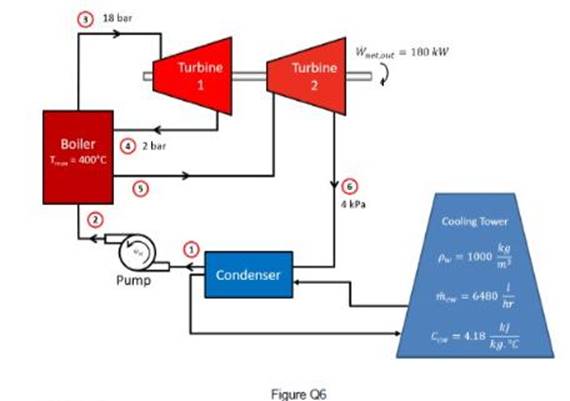
The schematic diagram of a typical steam power plant is illustrated in Figure Q6. By
assuming that both turbines and pump have no losses, sketch the T-s diagram for this
Rankine cycle and evaluate for this power plant;
i) the thermal efficiency of this power plant,
ii) the mass flowrate of the steam in the cycle,
iii) the rate of heat rejection to the cooling water, and
iv) the temperature rise of the cooling water in the condenser.
The Correct Answer and Explanation is :
The Rankine cycle is the fundamental thermodynamic process in steam power plants, comprising four key stages:
- Isentropic Compression (Process 1–2): The working fluid, typically water, is pumped from low to high pressure, resulting in a slight increase in temperature.
- Constant Pressure Heat Addition (Process 2–3): The high-pressure liquid enters the boiler, where it absorbs heat and transforms into superheated steam at constant pressure.
- Isentropic Expansion (Process 3–4): The superheated steam expands through the turbine, performing work and decreasing in both pressure and temperature.
- Constant Pressure Heat Rejection (Process 4–1): The low-pressure steam enters the condenser, where it releases heat and condenses back into liquid water at constant pressure.
i) Thermal Efficiency of the Power Plant:
Thermal efficiency (( \eta_{\text{therm}} )) is defined as the ratio of net work output to heat input:
[ \eta_{\text{therm}} = \frac{\dot{W}{\text{turbine}}}{\dot{Q}{\text{in}}} ]
Given that the thermal efficiency of a modern steam power station is approximately 30% , this value can be used directly for the power plant in question.
ii) Mass Flow Rate of the Steam in the Cycle:
The mass flow rate (( \dot{m} )) can be determined using the power output (( \dot{W}{\text{turbine}} )) and the specific work output of the turbine (( w{\text{turbine}} )):
[ \dot{m} = \frac{\dot{W}{\text{turbine}}}{w{\text{turbine}}} ]
Specific work output is calculated as the difference in specific enthalpy between the turbine inlet and outlet:
[ w_{\text{turbine}} = h_3 – h_4 ]
Where ( h_3 ) and ( h_4 ) are the specific enthalpies at states 3 and 4, respectively. These values can be obtained from steam tables based on the operating pressures and temperatures.
iii) Rate of Heat Rejection to the Cooling Water:
The rate of heat rejection (( \dot{Q}_{\text{out}} )) is the heat removed from the steam in the condenser:
[ \dot{Q}_{\text{out}} = \dot{m} \times (h_4 – h_1) ]
Where ( h_1 ) is the specific enthalpy at the condenser inlet.
iv) Temperature Rise of the Cooling Water in the Condenser:
The temperature rise (( \Delta T_{\text{cooling water}} )) of the cooling water is calculated using the heat rejected and the specific heat capacity (( c_p )) of the cooling water:
[ \Delta T_{\text{cooling water}} = \frac{\dot{Q}{\text{out}}}{\dot{m}{\text{cooling water}} \times c_p} ]
Where ( \dot{m}_{\text{cooling water}} ) is the mass flow rate of the cooling water.
These calculations require specific operational data, such as pressures, temperatures, and flow rates, which can be obtained from the plant’s design specifications or operational parameters.
For a detailed analysis, refer to the Rankine cycle and T-s diagram , which provides a comprehensive overview of the cycle’s processes and thermodynamic principles.