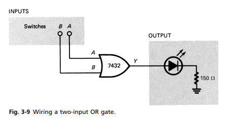
Wire the two-input OR gate (input switches, 7432 IC, and LED indicator-light assembly). See pin diagrams in Appendix A.
The Correct Answer and Explanation is :
To wire a two-input OR gate using input switches, the 7432 IC, and an LED indicator-light assembly, follow these steps:
Materials Needed:
- 7432 IC (Quad 2-input OR gate)
- Two switches (for inputs)
- LED indicator light
- Resistors (for current-limiting)
- Power supply (typically 5V)
- Breadboard and jumper wires
Pin Configuration for the 7432 IC (from the diagram):
- The 7432 IC contains four 2-input OR gates, each with the following pin layout:
- Pin 1, Pin 2: Input A and B for the first OR gate.
- Pin 3: Output for the first OR gate.
- Pin 4, Pin 5: Input A and B for the second OR gate.
- Pin 6: Output for the second OR gate, and so on.
For this circuit, you’ll use one OR gate from the IC.
Steps for Wiring the Circuit:
- Connect the Power:
- Pin 14 of the 7432 IC is the Vcc pin (5V), and Pin 7 is the ground (GND). Connect Vcc to the 5V power rail and GND to the ground rail on the breadboard.
- Connect Input Switches:
- Connect two switches to the inputs (Pin 1 and Pin 2 of the 7432 IC). One switch will act as input A, and the other will act as input B. Use pull-down resistors (10kΩ) between the switches and ground to ensure the inputs default to 0V when the switches are open.
- Connect the Output to the LED:
- Connect Pin 3 (the output of the OR gate) to the anode of an LED through a current-limiting resistor (typically 220Ω).
- Connect the cathode of the LED to ground.
- Testing:
- When both switches are OFF (0V), the output will be LOW (0V), so the LED will be off.
- When either or both switches are ON (5V), the output will be HIGH (5V), and the LED will turn on.
Explanation:
The 7432 IC contains multiple 2-input OR gates. The function of the OR gate is to output a HIGH signal (1) when either of its inputs (A or B) is HIGH, or both are HIGH. If both inputs are LOW, the output will be LOW.
In this circuit, the switches act as the inputs. If either switch is pressed, it supplies a HIGH signal to the corresponding input of the OR gate. The LED will indicate the output state of the OR gate, turning on when the output is HIGH (i.e., when at least one input switch is pressed).
This setup demonstrates how an OR gate works, where the output is true (1) if any input is true (1), aligning with the fundamental logic of an OR operation.