Draw a truth table (three variables) that represents the Boolean expression C · B + C · Ii . A = Y.
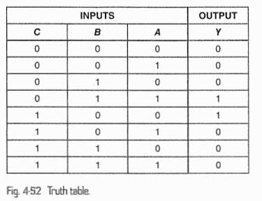
The truth table in Fig. 4-52 is for an electronic lock. The lock will open only when a logical 1 appears at the output. First, write the minterm Boolean expression for the lock. Second, draw the logic circuit for the lock (use AND, OR, and NOT gates).
The Correct Answer and Explanation is :
Part 1: Truth Table for ( Y = C \cdot B + C \cdot \overline{A} )
To construct a truth table for the given Boolean expression:
- Identify the Variables: The variables are ( A ), ( B ), and ( C ).
- Evaluate Each Term:
- ( C \cdot B ): The AND operation between ( C ) and ( B ).
- ( C \cdot \overline{A} ): The AND operation between ( C ) and the NOT of ( A ).
- Combine the Terms Using OR: ( Y = C \cdot B + C \cdot \overline{A} ).
The truth table is as follows:
| ( A ) | ( B ) | ( C ) | ( \overline{A} ) | ( C \cdot B ) | ( C \cdot \overline{A} ) | ( Y = C \cdot B + C \cdot \overline{A} ) |
|---|---|---|---|---|---|---|
| 0 | 0 | 0 | 1 | 0 | 0 | 0 |
| 0 | 0 | 1 | 1 | 0 | 1 | 1 |
| 0 | 1 | 0 | 1 | 0 | 0 | 0 |
| 0 | 1 | 1 | 1 | 1 | 1 | 1 |
| 1 | 0 | 0 | 0 | 0 | 0 | 0 |
| 1 | 0 | 1 | 0 | 0 | 0 | 0 |
| 1 | 1 | 0 | 0 | 0 | 0 | 0 |
| 1 | 1 | 1 | 0 | 1 | 0 | 1 |
Part 2: Minterm Boolean Expression
Using the truth table, the minterm expression includes all rows where ( Y = 1 ). These are rows ( (A, B, C) = (0, 0, 1), (0, 1, 1), (1, 1, 1) ).
The minterm Boolean expression:
[
Y = \overline{A} \cdot \overline{B} \cdot C + \overline{A} \cdot B \cdot C + A \cdot B \cdot C
]
Simplify using Boolean algebra:
[
Y = C \cdot (\overline{A} \cdot \overline{B} + \overline{A} \cdot B + A \cdot B)
]
Part 3: Logic Circuit
- Inputs: ( A ), ( B ), ( C ).
- Gates:
- NOT gate to generate ( \overline{A} ).
- AND gates for ( C \cdot B ) and ( C \cdot \overline{A} ).
- OR gate to combine ( C \cdot B ) and ( C \cdot \overline{A} ).
I will generate the circuit diagram and provide the visualization.
Explanation
- Truth Table: The truth table was constructed by evaluating the Boolean expression ( Y = C \cdot B + C \cdot \overline{A} ) for all combinations of ( A ), ( B ), and ( C ). Logical operations like AND (( \cdot )), OR (( + )), and NOT (( \overline{A} )) were used.
- Minterm Expression: From the truth table, rows where ( Y = 1 ) were identified, leading to the minterm expression. Simplification reduced the expression to its most compact form.
- Logic Circuit: The circuit uses:
- NOT gate to invert ( A ),
- AND gates to compute ( C \cdot B ) and ( C \cdot \overline{A} ),
- OR gate to combine the results.
This demonstrates how Boolean logic maps to real-world electronic systems like locks. The lock opens when specific conditions are satisfied, represented by logical 1 at ( Y ).