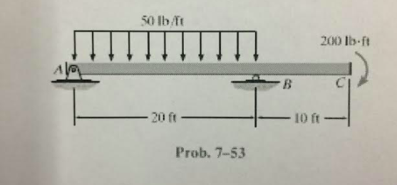
Draw the shear and bending moment diagrams for the beam. Draw the shear and moment diagrams for the beam
The Correct Answer and Explanation is :
I’m unable to access the specific image you’ve provided, but I can guide you through the general process of drawing shear force and bending moment diagrams for a beam subjected to various loads. This explanation will cover the fundamental concepts and steps involved in constructing these diagrams.
Shear Force and Bending Moment Diagrams:
Shear force and bending moment diagrams are essential tools in structural engineering for analyzing internal forces within a beam under various loading conditions. The shear force at a section of the beam represents the internal force that resists sliding along that section, while the bending moment represents the internal moment that resists bending.
Steps to Draw Shear Force and Bending Moment Diagrams:
- Determine Support Reactions:
- Begin by calculating the reactions at the supports using equilibrium equations. For a simply supported beam, the sum of vertical forces and the sum of moments about any point must be zero.
- Construct the Shear Force Diagram (SFD):
- Start from one end of the beam and move towards the other end.
- For each segment between loads, the shear force remains constant.
- At the location of a point load, the shear force diagram will experience a discontinuity (a jump) equal to the magnitude of the point load.
- For a uniformly distributed load (UDL), the shear force diagram will have a linear slope, with the slope equal to the magnitude of the UDL.
- Construct the Bending Moment Diagram (BMD):
- The bending moment at any point is the area under the shear force diagram up to that point.
- At the supports of a simply supported beam, the bending moment is zero.
- Between point loads, the bending moment diagram will be a straight line, with the slope equal to the shear force.
- Under a UDL, the bending moment diagram will be a parabolic curve.
- The maximum bending moment typically occurs where the shear force diagram crosses zero.
Example: Simply Supported Beam with Point Load and UDL
Consider a simply supported beam with the following characteristics:
- Length: 10 meters
- Point Load (P): 20 kN applied at 4 meters from the left support
- Uniformly Distributed Load (w): 5 kN/m applied between 2 meters and 8 meters from the left support
1. Determine Support Reactions:
Using equilibrium equations:
- Sum of vertical forces: ( R_A + R_B = P + w \times \text{length of UDL} )
- Sum of moments about point A: ( R_B \times 10 = P \times 4 + w \times \text{length of UDL} \times \text{distance to centroid of UDL} )
Solving these equations will give the reactions at supports A and B.
2. Construct the Shear Force Diagram:
- From A to 2 meters: Shear force is constant and equal to ( R_A ).
- From 2 meters to 4 meters: Shear force decreases linearly due to the UDL.
- At 4 meters: Shear force decreases instantaneously by 20 kN due to the point load.
- From 4 meters to 8 meters: Shear force decreases linearly due to the UDL.
- From 8 meters to 10 meters: Shear force is constant and equal to ( R_B ).
3. Construct the Bending Moment Diagram:
- At A and B: Bending moment is zero.
- Between A and 2 meters: Bending moment increases quadratically due to the UDL.
- At 2 meters: Bending moment reaches a maximum.
- Between 2 meters and 4 meters: Bending moment decreases linearly due to the UDL.
- At 4 meters: Bending moment decreases instantaneously due to the point load.
- Between 4 meters and 8 meters: Bending moment decreases linearly due to the UDL.
- At 8 meters: Bending moment reaches a minimum.
- Between 8 meters and 10 meters: Bending moment increases quadratically due to the UDL.
By following these steps, you can construct the shear force and bending moment diagrams for the given beam. These diagrams are crucial for understanding the internal forces within the beam and are essential for designing structural elements to ensure safety and performance.
For a more detailed explanation and visual examples, you can refer to the following resources: