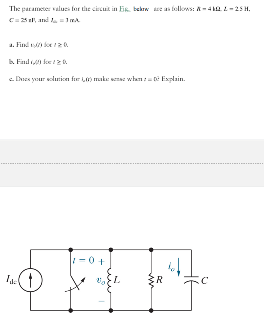
The parameter values for the circuit below are as follows: R=4kO, L=2.5H, C=25nF, and Idc=3mA.
Find vo(t) for t=0.
Find io(t) for t=0.
Does your solution for io(t) make sense when t=0? Explain.
The correct answer and explanation is :
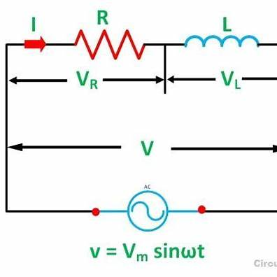
In an RL series circuit, a resistor (R) and an inductor (L) are connected in series with a direct current (DC) voltage source. When the circuit is powered on at time t = 0, the current does not immediately reach its maximum value due to the inductor’s opposition to changes in current. This opposition is characterized by the circuit’s time constant, τ, defined as τ = L/R.
Given Parameters:
- Resistance, R = 4 kΩ = 4000 Ω
- Inductance, L = 2.5 H
- DC Current Source, I_dc = 3 mA = 0.003 A
Time Constant Calculation:
The time constant τ is calculated as:
[ \tau = \frac{L}{R} = \frac{2.5\,\text{H}}{4000\,\Omega} = 0.000625\,\text{seconds} = 625\,\mu\text{s} ]
Current Through the Circuit (i(t)):
At the moment the circuit is energized (t = 0), the current i(t) increases from zero and asymptotically approaches its steady-state value, I_dc, following the exponential relationship:
[ i(t) = I_{\text{dc}} \left( 1 – e^{-\frac{t}{\tau}} \right) ]
At t = 0:
[ i(0) = 0.003\,\text{A} \left( 1 – e^{-\frac{0}{0.000625}} \right) = 0.003\,\text{A} \times (1 – 1) = 0\,\text{A} ]
Therefore, at the instant the circuit is activated, the current i(0) is 0 A.
Voltage Across the Resistor (v_R(t)):
The voltage across the resistor is given by Ohm’s law:
[ v_R(t) = R \times i(t) ]
At t = 0:
[ v_R(0) = 4000\,\Omega \times 0\,\text{A} = 0\,\text{V} ]
Thus, the voltage across the resistor at the moment the circuit is energized is 0 V.
Does the Solution for i(t) at t = 0 Make Sense?
Yes, the solution is consistent with the behavior of RL circuits. At the moment a DC voltage is applied (t = 0), the inductor opposes any sudden change in current, resulting in an initial current of 0 A. Over time, the current increases gradually, approaching the steady-state value determined by the DC source and resistance, following the exponential growth described by the time constant τ. This behavior aligns with the natural response of RL circuits to a step input.
Explanation:
When a DC voltage is first applied to an RL series circuit, the inductor generates a back electromotive force (EMF) that opposes the increase in current. This opposition causes the current to rise gradually rather than instantaneously. The time constant τ characterizes how quickly the current reaches its steady-state value; a larger τ results in a slower rise. In this scenario, with τ = 625 μs, the current increases to approximately 63% of its final value in that time. After about 5τ (3.125 ms), the current is virtually at its maximum value, with the inductor’s opposition having diminished significantly.
This analysis is crucial in applications where controlling the rate of current change is important, such as in power supplies and signal processing circuits.