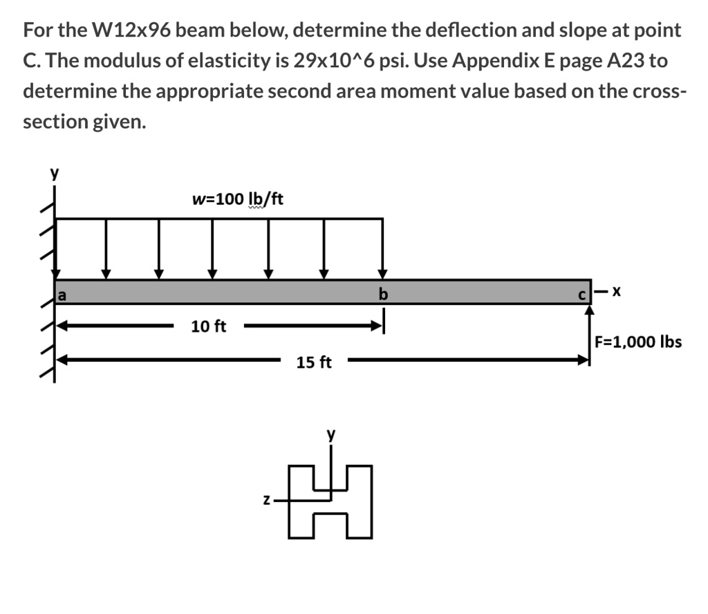
For the W12x96 beam below, determine the deflection and slope at point C. The modulus of elasticity is 29X10
psi. Use Appendix E page A23 to determine the appropriate second area moment value based on the cross- section given
The Correct Answer and Explanation is:
Here is the solution for the beam analysis problem.
Final Answer
The deflection at point C is v_C = -0.0954 inches (downward).
The slope at point C is θ_C = -0.000770 radians (clockwise).
Explanation
To determine the deflection and slope at the free end (point C) of the cantilever beam, the principle of superposition is applied. This method allows for the complex loading to be broken down into simpler, standard cases. The total deflection and slope are the algebraic sum of the deflections and slopes from each individual case.
1. System Properties and Unit Conversion
First, the necessary properties are identified and converted to consistent units (pounds and inches).
- Modulus of Elasticity (E): E = 29 x 10^6 lb/in²
- Moment of Inertia (I): For a W12x96 beam, the bending occurs about the strong (x-x) axis. From standard steel tables (equivalent to the specified Appendix), the moment of inertia is I_x = 833 in⁴.
- Loads and Dimensions:
- Distributed load, w = 100 lb/ft = 8.333 lb/in
- Concentrated load, F = 1,000 lb
- Length of distributed load, L_ab = 10 ft = 120 in
- Total beam length, L_ac = 15 ft = 180 in
2. Superposition Case 1: Effect of the Distributed Load (w)
The distributed load acts from point A to B. The deflection and slope at point C are found by first calculating these values at point B and then extending them along the unloaded segment BC.
- The slope at B (θ_B1) is:
θ_B1 = -w * L_ab³ / (6 * E * I) = -(8.333)(120)³ / (6 * 29×10⁶ * 833) = -0.0000993 rad - The deflection at B (v_B1) is:
v_B1 = -w * L_ab⁴ / (8 * E * I) = -(8.333)(120)⁴ / (8 * 29×10⁶ * 833) = -0.00894 in - The slope at C is the same as at B (θ_C1 = θ_B1). The deflection at C is the deflection at B plus the slope at B multiplied by the length of the segment BC (180 – 120 = 60 in).
v_C1 = v_B1 + θ_B1 * (L_ac – L_ab) = -0.00894 + (-0.0000993)(60) = -0.0149 in
3. Superposition Case 2: Effect of the Concentrated Load (F)
This case involves a standard cantilever beam with a point load at its free end (C).
- The slope at C (θ_C2) is:
θ_C2 = -F * L_ac² / (2 * E * I) = -(1000)(180)² / (2 * 29×10⁶ * 833) = -0.000671 rad - The deflection at C (v_C2) is:
v_C2 = -F * L_ac³ / (3 * E * I) = -(1000)(180)³ / (3 * 29×10⁶ * 833) = -0.0805 in
4. Total Deflection and Slope
The final results are obtained by summing the contributions from both cases.
- Total Deflection at C (v_C):
v_C = v_C1 + v_C2 = -0.0149 in + (-0.0805 in) = -0.0954 in - Total Slope at C (θ_C):
θ_C = θ_C1 + θ_C2 = -0.0000993 rad + (-0.000671 rad) = -0.000770 rad