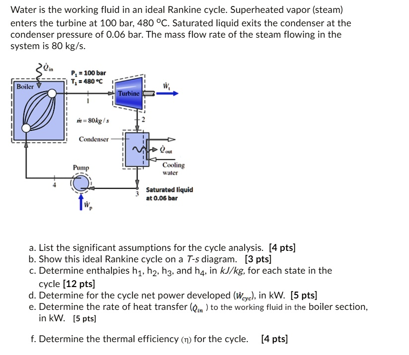
Water is the working fluid in an ideal Rankine cycle. Superheated vapor (steam) enters the turbine at 100 bar and 480°C. Saturated liquid exits the condenser at a pressure of 0.06 bar. The mass flow rate of the steam flowing in the system is 80 kg/s. P = 100 bar T = 480°C Boiler Turbine 1 m = 80 kg/s Condenser Pump Cooling water Saturated liquid at 0.06 bar a. List the significant assumptions for the cycle analysis. [4 pts] b. Show this ideal Rankine cycle on a T-s diagram. [3 pts] c. Determine enthalpies h1, h2, h3, and h4, in kJ/kg, for each state in the cycle. [12 pts] d. Determine the net power developed (wiyc) for the cycle, in kW. [5 pts] e. Determine the rate of heat transfer (Qim) to the working fluid in the boiler section, in kW. [5 pts] f. Determine the thermal efficiency (n) for the cycle. [4 pts]
This problem requires the analysis of an ideal Rankine cycle, which is the fundamental thermodynamic cycle that models the operation of steam turbine power plants. The analysis involves applying the first law of thermodynamics to each component (boiler, turbine, condenser, pump) operating at steady state. The “ideal” nature of the cycle implies that the turbine and pump operate isentropically (without any change in entropy), and there are no pressure losses in the boiler and condenser. By determining the properties of the working fluid (water) at the four key states of the cycle, we can calculate the cycle’s net power output, heat input, and overall thermal efficiency.
a. List the significant assumptions for the cycle analysis.
For the analysis of an ideal Rankine cycle, the following assumptions are made:
- Steady State: The cycle operates under steady-state conditions.
- Isentropic Processes: The turbine and pump are assumed to operate isentropically, meaning they are both adiabatic (no heat transfer) and reversible (no internal irreversibilities).
- Isobaric Processes: Heat addition in the boiler and heat rejection in the condenser occur at constant pressure (no pressure drops).
- Negligible Kinetic and Potential Energy: Changes in the kinetic and potential energy of the working fluid are considered negligible across all components.
b. Show this ideal Rankine cycle on a T-s diagram.
The T-s (Temperature-Entropy) diagram for this ideal Rankine cycle is shown below.
- Process 1 → 2: Isentropic (constant entropy) expansion of superheated steam through the turbine.
- Process 2 → 3: Isobaric (constant pressure) heat rejection in the condenser as the fluid condenses from a saturated mixture to a saturated liquid.
- Process 3 → 4: Isentropic (constant entropy) compression of the saturated liquid to the boiler pressure by the pump.
- Process 4 → 1: Isobaric (constant pressure) heat addition in the boiler, where the compressed liquid is heated, vaporized, and then superheated to the turbine inlet temperature.
c. Determine enthalpies h₁, h₂, h₃, and h₄, in kJ/kg, for each state in the cycle.
We use steam tables to find the enthalpy at each state.
- State 1 (Turbine Inlet):
Given: P₁ = 100 bar, T₁ = 480 °C (Superheated vapor)
From superheated steam tables, interpolating between 450 °C and 500 °C at 100 bar (10 MPa):
h₁ = 3322.0 kJ/kg
s₁ = 6.5285 kJ/kg·K - State 2 (Turbine Outlet):
Given: P₂ = 0.06 bar. Since the process is isentropic, s₂ = s₁ = 6.5285 kJ/kg·K.
At 0.06 bar from saturated steam tables:
s_f = 0.5210 kJ/kg·K, s_g = 8.3291 kJ/kg·K
Since s_f < s₂ < s_g, State 2 is a two-phase mixture. The quality (x₂) is:
x₂ = (s₂ – s_f) / (s_g – s_f) = (6.5285 – 0.5210) / (8.3291 – 0.5210) = 0.7694
Now, we find h₂ using the quality:
h₂ = h_f + x₂ * h_fg = 151.53 + (0.7694)(2415.4) = 2010.0 kJ/kg - State 3 (Condenser Outlet/Pump Inlet):
Given: P₃ = 0.06 bar, Saturated liquid.
From saturated steam tables at 0.06 bar:
h₃ = h_f = 151.5 kJ/kg
Also, v₃ = v_f = 0.0010064 m³/kg (for pump work calculation). - State 4 (Pump Outlet/Boiler Inlet):
The pump work, w_p, increases the enthalpy from h₃ to h₄.
w_p ≈ v₃(P₄ – P₃) = (0.0010064 m³/kg)(100 bar – 0.06 bar) * (100 kPa/1 bar)
w_p = 10.1 kJ/kg
h₄ = h₃ + w_p = 151.5 kJ/kg + 10.1 kJ/kg = 161.6 kJ/kg
d. Determine for the cycle the net power developed (Ẇ_cycle), in kW.
Net power is the power from the turbine minus the power consumed by the pump.
Ẇ_cycle = Ẇ_t – Ẇ_p = ṁ[(h₁ – h₂) – (h₄ – h₃)]
Ẇ_cycle = (80 kg/s ) * [(3322.0 – 2010.0) kJ/kg – (161.6 – 151.5) kJ/kg]
Ẇ_cycle = (80 kg/s ) * [1312.0 kJ/kg – 10.1 kJ/kg]
Ẇ_cycle = (80 kg/s ) * (1301.9 kJ/kg) = 104,152 kW (or 104.2 MW)
e. Determine the rate of heat transfer (Q̇_in) to the working fluid in the boiler section, in kW.
The rate of heat transfer into the boiler is:
Q̇_in = ṁ(h₁ – h₄)
Q̇_in = (80 kg/s ) * (3322.0 – 161.6) kJ/kg
Q̇_in = (80 kg/s ) * (3160.4 kJ/kg) = 252,832 kW (or 252.8 MW)
f. Determine the thermal efficiency (η) for the cycle.
The thermal efficiency is the ratio of the net work output to the heat input.
η = Ẇ_cycle / Q̇_in
η = 104,152 kW / 252,832 kW
η = 0.412
η = 41.2%