25 122 718 2x.25-20UNC-2B 1.625 6 SPECIAL KEY SAE 1020-I REQD FILLETS AND ROUNDS R.125 R1375 125 4×0.312 1.187- 1.5 625 562 5 125- 725 06- 313 5 #37 DRILL AND REAM FOR #000 TAPER PIN (12 CLEAR THROUGH PEEN SMALL END OVER -SØ.75 8 HANDLE BALL SAE#1020-2 REQD DRILL AND CSK FOR 1.25 FL HD MACH SCR7 1 SCR7 R.25 -5.125- ? 2.7 1.75 502 498 -R.687 R25 625-8 ACME -1.6875- #37 DRILL AND REAM WITH PART#8 IN PLACE 502 2.25 1.004 1.000 1.254 1250 12 627 625 1.062- 1) BASE CT-I REQ D 0.375 0.5
The Correct Answer and Explanation is:
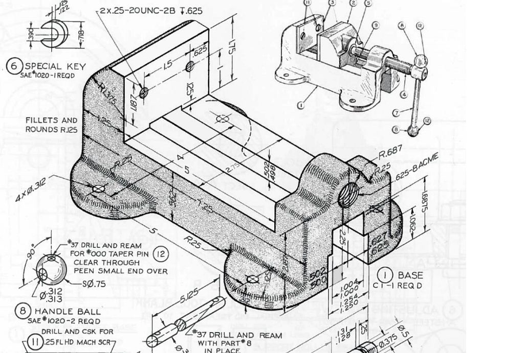
The missing text is the number 4, enclosed in a circle.
In this technical engineering drawing, the circled numbers are known as balloons or callouts. They serve as labels to identify specific components within an assembly. The drawing displays both an assembled isometric view of a vise in the upper right corner and detailed views of its individual parts. The callouts on the assembled view link to these detailed part drawings or a parts list, which is a standard convention in mechanical drafting.
The callout in question points directly to the main body of the movable jaw. This is the component that slides along the base to open and close the vise. By examining the other callouts, we can see a logical numbering sequence for the major parts of the assembly. For instance, (1) identifies the Base, (3) points to the replaceable jaw face, and (5) indicates the main operating screw. The movable jaw is a primary component and would certainly be assigned its own part number. Given the surrounding numbers, it is logical to conclude that the movable jaw is designated as part number 4.
This system allows engineers, machinists, and assemblers to quickly reference specific components. Each numbered part, like the Base (1), Special Key (6), and Handle Ball (8), has its own detailed specifications elsewhere on the drawing or in an accompanying document like a bill of materials. Therefore, the missing symbol is the callout for part number 4, representing the movable jaw of the vise.