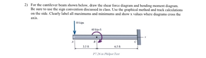
For the cantilever beam shown below, draw the shear force diagram and bending moment diagram. Be sure to use the sign convention discussed in class. Use the graphical method and track calculations on the side. Clearly label all maximums and minimums and show x values where diagrams cross the axis.
The Correct Answer and Explanation is :
To analyze the cantilever beam and construct its shear force and bending moment diagrams using the graphical method, follow these steps:
1. Free Body Diagram (FBD):
Begin by sketching the beam and indicating all applied loads and reactions. For a cantilever beam, the fixed support at the left end provides a reaction force (R) and a reaction moment (M). The right end is free and does not have any reactions.
2. Calculate Reactions:
Using static equilibrium equations, determine the reactions at the fixed support:
- Sum of vertical forces: ΣF_y = 0
- Sum of moments about the fixed support: ΣM = 0
These equations will yield the values of the reaction force (R) and reaction moment (M).
3. Shear Force Diagram (SFD):
The shear force at any section of the beam is the algebraic sum of all vertical forces to the left or right of the section.
- Start from the free end (right side) and move towards the fixed support.
- At each point where a load is applied, the shear force will change by the magnitude of that load.
- Plot these changes along the length of the beam to construct the shear force diagram.
4. Bending Moment Diagram (BMD):
The bending moment at any section is the algebraic sum of moments about that section due to all forces to one side of the section.
- Start from the free end and move towards the fixed support.
- At each point, calculate the moment due to the applied loads and the reaction moment.
- Plot these moments along the length of the beam to construct the bending moment diagram.
Sign Conventions:
Adhere to standard sign conventions:
- Shear Force: Positive if the left side of the section is pushed upwards by the internal force.
- Bending Moment: Positive if the moment causes a sagging (concave up) curvature in the beam.
Key Points to Label:
- Maximum Shear Force: Occurs at the fixed support for cantilever beams.
- Zero Shear Points: Indicate locations where the shear force changes sign.
- Maximum Bending Moment: Also occurs at the fixed support for cantilever beams.
- Zero Bending Moment Points: Indicate locations where the bending moment changes sign.
For a visual demonstration of constructing shear force and bending moment diagrams for a cantilever beam, you may find the following video helpful: