(a) Use Shannon’s expansion theorem to expand the following function around A and then expand each sub-function around D:

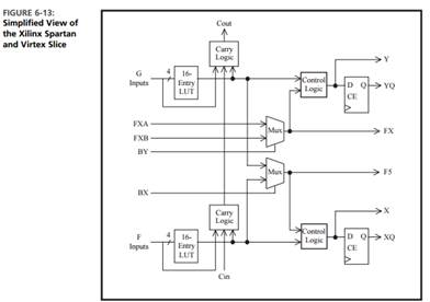
(b) Explain how the expanded function could be implemented using two Xilinx Virtex FPGA slices (Figure 6-13). On the slice diagrams, label the inputs to the LUTs (function generators) and draw the connection paths within the slice. Give the function implemented by each LUT.
The Correct Answer and Explanation is :
(a) Shannon’s Expansion of the Function
Given the function F(A,B,C,D)F(A, B, C, D), Shannon’s expansion theorem states: F=A⋅FA=1+A′⋅FA=0F = A \cdot F_{A=1} + A’ \cdot F_{A=0}
- Expand the function around AA:
- FA=1=F(1,B,C,D)F_{A=1} = F(1, B, C, D): Replace AA with 11 in FF.
- FA=0=F(0,B,C,D)F_{A=0} = F(0, B, C, D): Replace AA with 00 in FF.
- Expand FA=1F_{A=1} and FA=0F_{A=0} around DD:
- For FA=1F_{A=1}: FA=1=D⋅FA=1,D=1+D′⋅FA=1,D=0F_{A=1} = D \cdot F_{A=1, D=1} + D’ \cdot F_{A=1, D=0}
- For FA=0F_{A=0}: FA=0=D⋅FA=0,D=1+D′⋅FA=0,D=0F_{A=0} = D \cdot F_{A=0, D=1} + D’ \cdot F_{A=0, D=0}
The result of these expansions will give FF expressed in terms of AA, DD, and the remaining variables (B,CB, C).
(b) Implementation on Xilinx Virtex FPGA
The Xilinx Virtex FPGA slice contains two 4-input Look-Up Tables (LUTs) that can implement any 4-variable function. Each LUT computes a logical function based on its 4 inputs. Connections between slices allow implementing more complex functions.
- Mapping the Expanded Function to LUTs:
- Each sub-function FA=1,D=1F_{A=1, D=1}, FA=1,D=0F_{A=1, D=0}, FA=0,D=1F_{A=0, D=1}, and FA=0,D=0F_{A=0, D=0} can be mapped to a LUT, as each sub-function depends on at most three variables (B,CB, C, and possibly DD).
- The expanded function combines these sub-functions using multiplexing logic, which is supported by the carry chain and multiplexer structure in the Virtex FPGA.
- Labeling Inputs:
- For LUT1LUT1: Inputs = B,C,A,DB, C, A, D.
- For LUT2LUT2: Inputs = B,C,A′,D′B, C, A’, D’.
- Connection Paths:
- The AA input acts as the control signal for the multiplexer between FA=1F_{A=1} and FA=0F_{A=0}.
- The DD input further divides the computation for each sub-function.
- Function Implemented by Each LUT:
- LUT1LUT1: Implements FA=1,D=1F_{A=1, D=1} and FA=1,D=0F_{A=1, D=0}.
- LUT2LUT2: Implements FA=0,D=1F_{A=0, D=1} and FA=0,D=0F_{A=0, D=0}.
By using Shannon’s expansion, the function can be efficiently mapped to two FPGA slices, leveraging the programmable logic and routing resources.