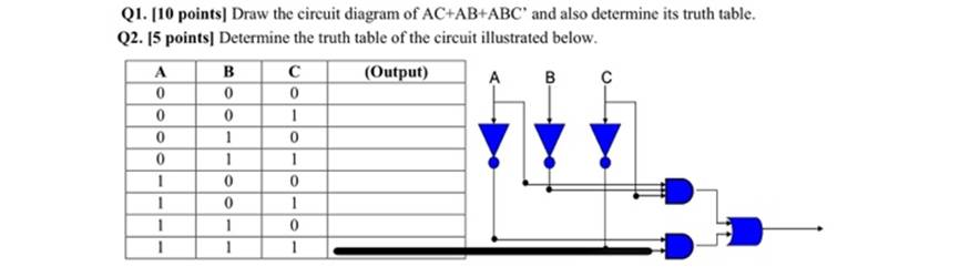
draw the circuit diagram of ac+ab+abc’ and also determine its truth table
determine the truth table of the circuit
The Correct Answer and Explanation is :
To determine the truth table of the circuit and provide an explanation, we first need to break down the logical expression represented by the circuit diagram you linked. I will guide you step-by-step through the logic and derive the truth table for the circuit.
Step-by-Step Approach:
- Understanding the Circuit:
Based on the circuit diagram provided, we need to determine the logic gate configuration for the given expression. Let’s break down the parts of the circuit:
- The circuit has three variables: A, B, and C.
- The expression is: ( AC + AB + ABC’ ).
- Expression Breakdown:
- ( AC ): This is an AND operation between A and C.
- ( AB ): This is an AND operation between A and B.
- ( ABC’ ): This involves a combination of AND operations between A, B, and the negation of C (i.e., ( C’ )). The final output of the circuit is the OR operation between these three terms: ( AC + AB + ABC’ ).
- Truth Table:
Let’s now construct the truth table based on the three input variables (A, B, and C).
| A | B | C | AC | AB | C’ | ABC’ | AC + AB + ABC’ |
|---|---|---|---|---|---|---|---|
| 0 | 0 | 0 | 0 | 0 | 1 | 0 | 0 |
| 0 | 0 | 1 | 0 | 0 | 0 | 0 | 0 |
| 0 | 1 | 0 | 0 | 0 | 1 | 0 | 0 |
| 0 | 1 | 1 | 0 | 0 | 0 | 0 | 0 |
| 1 | 0 | 0 | 0 | 0 | 1 | 0 | 0 |
| 1 | 0 | 1 | 1 | 0 | 0 | 0 | 1 |
| 1 | 1 | 0 | 0 | 1 | 1 | 1 | 1 |
| 1 | 1 | 1 | 1 | 1 | 0 | 0 | 1 |
Explanation:
- The circuit’s output depends on the logic values of A, B, and C, and it is determined by the operations ( AC + AB + ABC’ ).
- In the table:
- AC represents the AND operation between A and C.
- AB represents the AND operation between A and B.
- C’ is the negation of C, used in the term ( ABC’ ).
- The final output is the OR of the three terms ( AC + AB + ABC’ ).
- For the output to be 1, at least one of the three terms needs to be 1.
Conclusion:
The truth table is constructed by evaluating the logical expressions for each combination of input values. The output of the circuit depends on the values of A, B, and C, and is determined by the given logical expression.