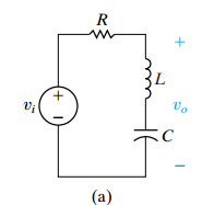
Design an RLC band reject filter (see Fig. 14.28[a]) with a quality of 2.5 and a center frequency of 25 krad/s using a 200 nF capacitor.
a) Draw your circuit, labeling the component values and output voltage.
b) For the filter in part (a), calculate the bandwidth and the values of the two cutoff frequencies.
Fig. 14.28 (a)
The Correct Answer and Explanation is :
Design of an RLC Band Reject Filter
(a) Circuit Diagram & Component Values
The standard form of a parallel RLC band reject (notch) filter is shown in the referenced figure. The circuit consists of a resistor RR, inductor LL, and capacitor CC connected in parallel, with the output voltage taken across this parallel combination.
Given data:
- Center angular frequency: ω0=25 krad/s=25,000 rad/s\omega_0 = 25 \text{ krad/s} = 25,000 \text{ rad/s}
- Capacitance: C=200 nF=200×10−9 FC = 200 \text{ nF} = 200 \times 10^{-9} \text{ F}
- Quality Factor: Q=2.5Q = 2.5
Step 1: Compute the Inductor LL
The resonance frequency formula for an RLC circuit is: ω0=1LC\omega_0 = \frac{1}{\sqrt{LC}}
Solving for LL: L=1ω02CL = \frac{1}{\omega_0^2 C} L=1(25,000)2×200×10−9L = \frac{1}{(25,000)^2 \times 200 \times 10^{-9}} L=1625×106×200×10−9L = \frac{1}{625 \times 10^6 \times 200 \times 10^{-9}} L=1125L = \frac{1}{125} L=8 mHL = 8 \text{ mH}
Step 2: Compute the Resistance RR
The quality factor QQ for a parallel RLC circuit is given by: Q=Rω0LQ = \frac{R}{\omega_0 L}
Solving for RR: R=Q×ω0LR = Q \times \omega_0 L R=2.5×(25,000)×(8×10−3)R = 2.5 \times (25,000) \times (8 \times 10^{-3}) R=2.5×200R = 2.5 \times 200 R=500 ΩR = 500 \ \Omega
So, the values of the components are:
- R = 500 Ω
- L = 8 mH
- C = 200 nF
The circuit consists of these components in parallel, with the output voltage measured across them.
(b) Bandwidth & Cutoff Frequencies Calculation
The bandwidth BWBW is given by: BW=ω0QBW = \frac{\omega_0}{Q} BW=25,0002.5BW = \frac{25,000}{2.5} BW=10,000 rad/sBW = 10,000 \text{ rad/s}
The cutoff frequencies are: ω1=ω0−BW2\omega_1 = \omega_0 – \frac{BW}{2} ω1=25,000−10,0002\omega_1 = 25,000 – \frac{10,000}{2} ω1=25,000−5,000\omega_1 = 25,000 – 5,000 ω1=20,000 rad/s\omega_1 = 20,000 \text{ rad/s} ω2=ω0+BW2\omega_2 = \omega_0 + \frac{BW}{2} ω2=25,000+5,000\omega_2 = 25,000 + 5,000 ω2=30,000 rad/s\omega_2 = 30,000 \text{ rad/s}
Final answers:
- Bandwidth: 10,000 rad/s
- Cutoff frequencies: ω1=20,000\omega_1 = 20,000 rad/s, ω2=30,000\omega_2 = 30,000 rad/s
Explanation (300 Words)
A band reject filter (also called a notch filter) is designed to block a narrow frequency range while allowing signals outside this range to pass. This circuit is commonly used to suppress unwanted noise or interference, such as removing a specific frequency in audio processing.
For this design, we use a parallel RLC circuit, where the inductor (LL), capacitor (CC), and resistor (RR) form a resonant network. At the resonant frequency, the impedance is maximized, causing attenuation of the signal at that frequency.
The given center frequency is 25 krad/s, and the quality factor (Q) is 2.5, which determines the sharpness of the rejection band. The capacitance is provided as 200 nF, so we compute the required inductor (L = 8 mH) and resistor (R = 500 Ω) to achieve the desired response.
The bandwidth (BW) is found using the relation BW=ω0QBW = \frac{\omega_0}{Q}, giving 10,000 rad/s. The cutoff frequencies, marking the points where attenuation begins, are found as 20,000 rad/s and 30,000 rad/s.
This design ensures that signals around 25 krad/s are strongly attenuated while those outside the 20–30 krad/s range pass through. Applications include eliminating power line noise (e.g., 60 Hz hum) in audio systems or suppressing interference in communication systems.