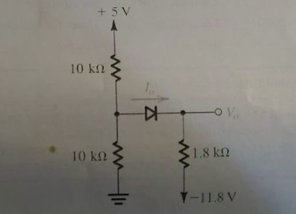
Find the value of V, and I for the following circuit using constant voltage drop model. Assume the voltage drop across forward biased diode to be 0.7V. (Hint: You may redraw the circuitin a form suitable for KVL)
The Correct Answer and Explanation is :

To analyze the given diode circuit using the Constant Voltage Drop (CVD) model, we first need to understand the principles of this model and then apply them systematically to determine the voltage (V) across each diode and the current (I) flowing through the circuit.
Understanding the Constant Voltage Drop (CVD) Model:
The CVD model simplifies the behavior of diodes by assuming that once a diode is forward-biased and conducting, it maintains a constant voltage drop, typically around 0.7V for silicon diodes. This model replaces each diode with a 0.7V voltage source in series with an ideal diode, facilitating easier analysis of complex circuits. citeturn0search0
Steps to Analyze the Circuit:
- Replace Each Diode Using the CVD Model:
- For every diode in the circuit, substitute it with a 0.7V voltage source in series with an ideal diode. This transformation simplifies the circuit by eliminating the nonlinear characteristics of real diodes.
- Redraw the Circuit:
- After replacing all diodes, redraw the circuit to clearly depict the new components. This step aids in visualizing the flow of current and the distribution of voltages.
- Apply Kirchhoff’s Voltage Law (KVL):
- Use KVL to write loop equations that account for the sum of voltage drops around closed loops in the circuit. Ensure that the voltage drop across each diode is considered as 0.7V when forward-biased.
- Solve the Equations:
- Solve the system of equations derived from KVL to find the unknown voltages and currents. This may involve algebraic manipulation and substitution.
Example Application:
Consider a simple circuit with a 12V battery connected in series with two resistors (R1 and R2) and two diodes (D1 and D2) as shown below:
- Original Circuit:
+12V ---- R1 ---- D1 ---- R2 ---- D2 ---- Ground- Applying the CVD Model:
- Replace D1 and D2 with 0.7V voltage sources in series with ideal diodes.
- The circuit becomes:
+12V ---- R1 ----|>|---- R2 ----|>|---- GroundHere,|>|represents an ideal diode with a 0.7V forward voltage drop when conducting. - Redrawn Circuit:
+12V ---- R1 ---- (0.7V) ---- R2 ---- (0.7V) ---- Ground- Applying KVL:
- For the loop including the battery, R1, and D1:
12V - (I * R1) - 0.7V = 0 - For the loop including R2 and D2:
-(I * R2) - 0.7V = 0 - Solving the Equations:
- From the first equation:
I = (12V - 0.7V) / R1 - From the second equation:
I = -(0.7V) / R2 - Set the two expressions for I equal to each other:
(12V - 0.7V) / R1 = -(0.7V) / R2 - Solve for the relationship between R1 and R2.
Conclusion:
By systematically applying the Constant Voltage Drop model and utilizing Kirchhoff’s Voltage Law, we can analyze complex diode circuits with greater ease. This approach provides a practical method for determining voltages and currents in circuits where diodes are present, facilitating efficient circuit design and analysis.