How are such components as coils and contacts identified and distinguished from others in a PLC schematic?
The correct answer and explanation is :
Answer:
In a PLC schematic, coils and contacts are identified and distinguished by their unique symbols and reference designations:
- Contacts: Represented by normally open (NO) or normally closed (NC) symbols in ladder logic. They are linked to input addresses such as I:0/1 (physical input) or internal memory bits (B3:0/1).
- Coils: Represented by an output coil symbol (a circle with a label) and are associated with output addresses like O:0/2 (physical output) or internal bits used for control logic.
Each contact or coil is labeled with a unique tag that corresponds to the PLC’s memory or I/O (Input/Output) mapping.
Explanation (300 Words)
In Programmable Logic Controller (PLC) schematics, distinguishing different components is crucial for understanding circuit operation. Ladder Logic Diagrams (LLDs) are commonly used to represent PLC circuits, resembling electrical relay logic.
1. Contacts Identification:
PLC contacts are used to represent input signals or internal memory states:
- Normally Open (NO) Contacts (—| |—): These close when the associated input or memory bit is activated.
- Normally Closed (NC) Contacts (—|/|—): These open when the associated input or memory bit is activated.
Each contact corresponds to an input device (e.g., push button, limit switch) or an internal relay.
2. Coils Identification:
PLC coils are output elements that control devices such as motors, solenoids, or relays.
- Coils are represented as (—( )—) and activated when the logic before them is true.
- Output addresses like O:0/0 or internal memory bits (B3:1/0) are used to reference them.
3. Distinguishing Coils from Contacts:
- Contacts are only conditions that check the status of inputs or internal relays.
- Coils perform actions, setting or resetting outputs when activated.
Conclusion:
By correctly identifying coils and contacts, engineers can efficiently troubleshoot and program PLC systems.
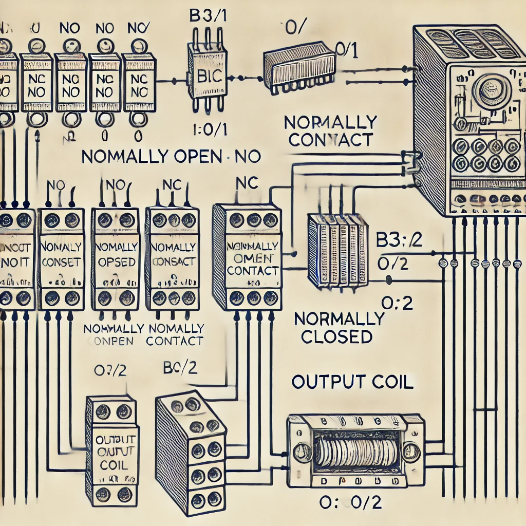
Here’s an example image of PLC contacts and coils in a ladder logic diagram: