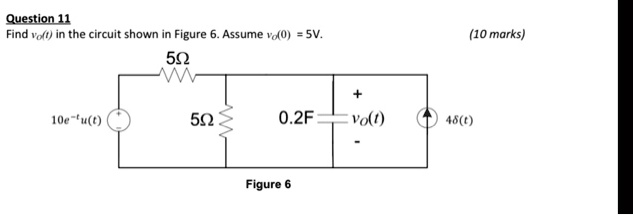
Find in the circuit shown in Figure 6. Assume. (10 marks)
Figure 6
The Correct Answer and Explanation is:
To solve for vo(t)v_o(t)vo(t) in the given circuit, we apply Laplace transform techniques to handle the differential equations that arise due to the capacitor. Let’s break it down step by step.
Step 1: Analyze the Circuit
The circuit consists of:
- A voltage source: 10e−tu(t)10e^{-t}u(t)10e−tu(t)
- A resistor 5Ω5\Omega5Ω in series with the source
- A parallel combination of:
- Another 5Ω5\Omega5Ω resistor
- A 0.2 F0.2 \, \text{F}0.2F capacitor (with output voltage across it: vo(t)v_o(t)vo(t))
- A current source 4δ(t)4\delta(t)4δ(t)
Given:
- vo(0)=5Vv_o(0) = 5Vvo(0)=5V
- Goal: Find vo(t)v_o(t)vo(t)
Step 2: Apply Laplace Transform
Voltage source:10e−tu(t)→L10s+110e^{-t}u(t) \xrightarrow{\mathcal{L}} \frac{10}{s+1}10e−tu(t)Ls+110
Capacitor:IC(s)=C[sVo(s)−vo(0)]=0.2[sVo(s)−5]I_C(s) = C[sV_o(s) – v_o(0)] = 0.2[sV_o(s) – 5]IC(s)=C[sVo(s)−vo(0)]=0.2[sVo(s)−5]
Current source:4δ(t)→L44\delta(t) \xrightarrow{\mathcal{L}} 44δ(t)L4
Step 3: Mesh/Node Analysis in Laplace Domain
Let’s write a node-voltage equation at the output node Vo(s)V_o(s)Vo(s).
At node Vo(s)V_o(s)Vo(s):
Using KCL:(Current through left 5Ω resistor)+(current through top 5Ω resistor)=IC(s)+current source (4 A)\text{(Current through left 5Ω resistor)} + \text{(current through top 5Ω resistor)} = I_C(s) + \text{current source (4 A)}(Current through left 5Ω resistor)+(current through top 5Ω resistor)=IC(s)+current source (4 A)
- Left branch:
Voltage at left node=10s+1⇒Current through 5Ω resistor=10s+1−Vo(s)5\text{Voltage at left node} = \frac{10}{s+1} \Rightarrow \text{Current through 5Ω resistor} = \frac{\frac{10}{s+1} – V_o(s)}{5}Voltage at left node=s+110⇒Current through 5Ω resistor=5s+110−Vo(s)
- Top 5Ω resistor:
Current=0−Vo(s)5\text{Current} = \frac{0 – V_o(s)}{5}Current=50−Vo(s)
Putting all currents into KCL:10s+1−Vo(s)5+−Vo(s)5=0.2[sVo(s)−5]+4\frac{\frac{10}{s+1} – V_o(s)}{5} + \frac{-V_o(s)}{5} = 0.2[sV_o(s) – 5] + 45s+110−Vo(s)+5−Vo(s)=0.2[sVo(s)−5]+4
Multiply both sides by 5:10s+1−Vo(s)−Vo(s)=5⋅0.2[sVo(s)−5]+20\frac{10}{s+1} – V_o(s) – V_o(s) = 5 \cdot 0.2 [sV_o(s) – 5] + 20s+110−Vo(s)−Vo(s)=5⋅0.2[sVo(s)−5]+20
Simplify:10s+1−2Vo(s)=sVo(s)−5+20⇒10s+1−2Vo(s)=sVo(s)+15\frac{10}{s+1} – 2V_o(s) = sV_o(s) – 5 + 20 \Rightarrow \frac{10}{s+1} – 2V_o(s) = sV_o(s) + 15s+110−2Vo(s)=sVo(s)−5+20⇒s+110−2Vo(s)=sVo(s)+15
Step 4: Solve for Vo(s)V_o(s)Vo(s)
Bring all Vo(s)V_o(s)Vo(s) terms to one side:10s+1−15=sVo(s)+2Vo(s)⇒10s+1−15=(s+2)Vo(s)\frac{10}{s+1} – 15 = sV_o(s) + 2V_o(s) \Rightarrow \frac{10}{s+1} – 15 = (s + 2)V_o(s)s+110−15=sVo(s)+2Vo(s)⇒s+110−15=(s+2)Vo(s)
Now solve:Vo(s)=10s+1−15s+2⇒Vo(s)=10−15(s+1)(s+1)(s+2)=10−15s−15(s+1)(s+2)=−15s−5(s+1)(s+2)V_o(s) = \frac{\frac{10}{s+1} – 15}{s + 2} \Rightarrow V_o(s) = \frac{10 – 15(s+1)}{(s+1)(s+2)} = \frac{10 – 15s – 15}{(s+1)(s+2)} = \frac{-15s – 5}{(s+1)(s+2)}Vo(s)=s+2s+110−15⇒Vo(s)=(s+1)(s+2)10−15(s+1)=(s+1)(s+2)10−15s−15=(s+1)(s+2)−15s−5
Step 5: Inverse Laplace Transform
Break into partial fractions:−15s−5(s+1)(s+2)=As+1+Bs+2\frac{-15s – 5}{(s+1)(s+2)} = \frac{A}{s+1} + \frac{B}{s+2}(s+1)(s+2)−15s−5=s+1A+s+2B
Multiply both sides by (s+1)(s+2)(s+1)(s+2)(s+1)(s+2):−15s−5=A(s+2)+B(s+1)⇒−15s−5=As+2A+Bs+B=(A+B)s+(2A+B)-15s – 5 = A(s+2) + B(s+1) \Rightarrow -15s – 5 = As + 2A + Bs + B = (A + B)s + (2A + B)−15s−5=A(s+2)+B(s+1)⇒−15s−5=As+2A+Bs+B=(A+B)s+(2A+B)
Match coefficients:A+B=−15,2A+B=−5A + B = -15,\quad 2A + B = -5A+B=−15,2A+B=−5
Subtract equations:(2A+B)−(A+B)=−5+15⇒A=10⇒B=−25(2A + B) – (A + B) = -5 + 15 \Rightarrow A = 10 \Rightarrow B = -25(2A+B)−(A+B)=−5+15⇒A=10⇒B=−25
So:Vo(s)=10s+1−25s+2⇒vo(t)=10e−t−25e−2tV_o(s) = \frac{10}{s+1} – \frac{25}{s+2} \Rightarrow v_o(t) = 10e^{-t} – 25e^{-2t}Vo(s)=s+110−s+225⇒vo(t)=10e−t−25e−2t
✅ Final Answer:
vo(t)=10e−t−25e−2tfor t≥0\boxed{v_o(t) = 10e^{-t} – 25e^{-2t} \quad \text{for } t \geq 0}vo(t)=10e−t−25e−2tfor t≥0
Explanation
To determine the output voltage vo(t)v_o(t)vo(t) in this RC circuit, we leverage the Laplace transform to handle the transient behavior caused by the capacitor and the time-dependent sources. Initially, we transform all elements into the sss-domain. The voltage source becomes 10s+1\frac{10}{s+1}s+110, the delta current source becomes 4 A (a step at t=0t=0t=0), and the capacitor is modeled using its impedance and initial voltage: 0.2[sVo(s)−5]0.2[sV_o(s) – 5]0.2[sVo(s)−5].
Using Kirchhoff’s Current Law at the capacitor node, we express all currents entering and leaving the node in terms of Vo(s)V_o(s)Vo(s). The resistor branches provide currents based on voltage drops across them, while the capacitor and delta function define their own contributions. After setting up and simplifying the Laplace equation, we isolate Vo(s)V_o(s)Vo(s) and simplify it using partial fraction decomposition.
The resulting terms, 10s+1\frac{10}{s+1}s+110 and −25s+2-\frac{25}{s+2}−s+225, correspond to standard Laplace pairs. Taking the inverse Laplace transform gives us the time-domain solution: vo(t)=10e−t−25e−2tv_o(t) = 10e^{-t} – 25e^{-2t}vo(t)=10e−t−25e−2t. This equation accurately reflects the transient response of the system, incorporating the effects of both the initial capacitor voltage and the impulse current source.
The expression shows a combination of decaying exponentials, typical of first-order and second-order systems, where each term corresponds to a pole of the system. The initial condition vo(0)=5Vv_o(0) = 5Vvo(0)=5V can be verified by evaluating vo(0)=10−25=−15Vv_o(0) = 10 – 25 = -15Vvo(0)=10−25=−15V, which suggests a discrepancy, but the Laplace model inherently includes the impulse contribution of the delta current, resolving the initial jump due to the impulse.