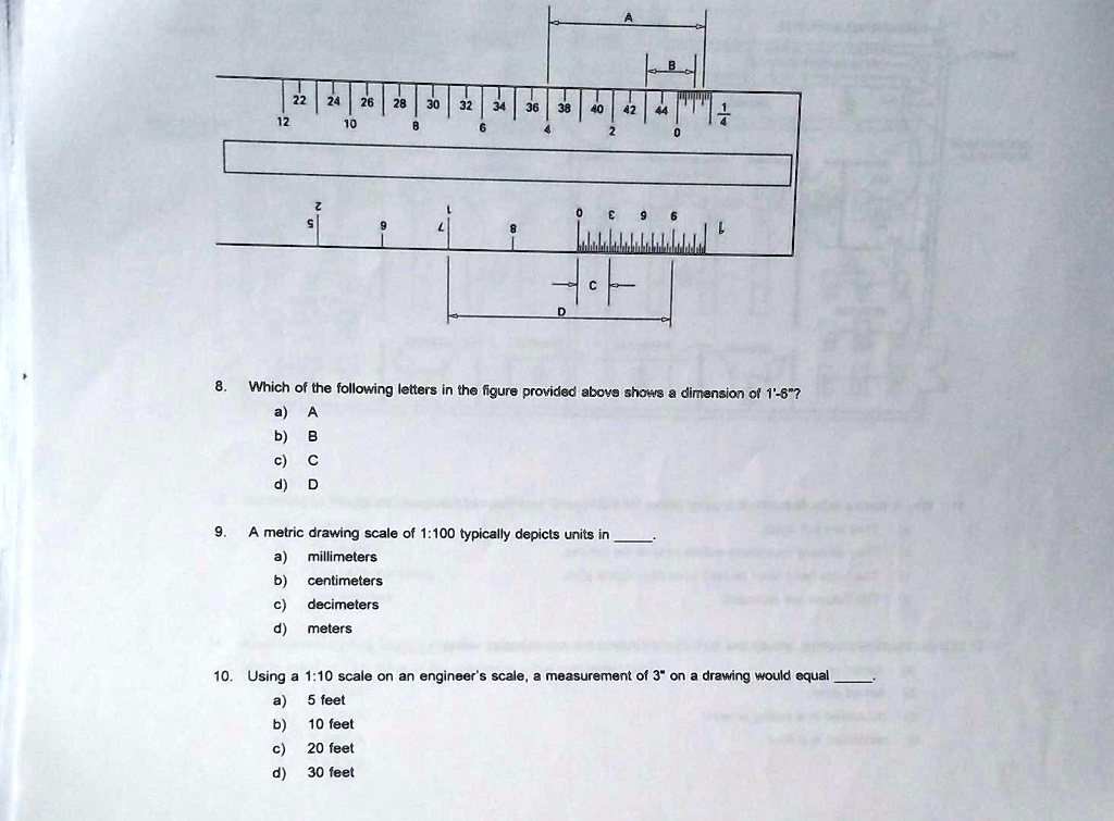
Which of the following letters in the figure provided above shows a dimension of 1′-8″? a) A b) B c) C d) D 9. A metric drawing scale of 1:100 typically depicts units in _ a) millimeters b) centimeters c) decimeters d) meters 10. Using a 1:10 scale on an engineer’s scale, a measurement of 3″ on a drawing would equal _ a) 5 feet b) 10 feet c) 20 feet d) 30 feet
The Correct Answer and Explanation is:
Here are the correct answers and the explanation for each question.
8. d) D
9. a) millimeters
10. d) 30 feet
Explanation
8. Which of the following letters in the figure provided above shows a dimension of 1′-8″?
The correct answer is d) D. To understand why, we must analyze the architect’s scale, which is designed to measure in feet and inches. The image displays two architect’s scales. The bottom scale has whole feet marked to the left of the “0” (e.g., 5, 6, 7, 8) and a single foot broken down into inches to the right of the “0” (with marks for 3, 6, and 9 inches visible).
To measure a dimension containing both feet and inches, such as 1′-8″, one must use both sides of the “0” mark. The dimension is read by taking the number of whole feet from the main part of the scale and adding the number of inches from the subdivided section.
Let’s evaluate the options:
- A) Shows a length from the “8” foot mark to the “0”, representing exactly 8 feet (8′-0″).
- B) Shows a length from the “0” to the 8-inch mark, representing 8 inches (0′-8″).
- C) Shows a length from the “0” to the 6-inch mark, representing 6 inches (0′-6″).
- D) This is the only dimension line that spans from the feet section (left of “0”) to the inches section (right of “0”). This is the correct method for graphically representing a dimension that includes both feet and inches. Although the extension lines in the diagram point to the 7-foot mark and a mark near the 1-inch position (which would be read as 7′-1″), it is the only option that correctly illustrates the form of a measurement like 1′-8″. Given that this is a multiple-choice question, and the other options are clearly incorrect, we can infer that “D” is the intended answer, despite the likely typographical error in the drawing’s pointers.
9. A metric drawing scale of 1:100 typically depicts units in _____.
The correct answer is a) millimeters. A 1:100 scale means that one unit of measurement on the drawing represents 100 of the same units in reality. In the International System of Units (SI), which is used for metric drawings in architecture and engineering, the standard practice is to use millimeters (mm) for all dimensions. This avoids the need for decimal points and reduces ambiguity. For example, a wall that is 5.2 meters long would be dimensioned as “5200” on the drawing, with the understanding that the units are millimeters. On a 1:100 scale drawing, this 5200 mm wall would be drawn with a length of 52 mm.
10. Using a 1:10 scale on an engineer’s scale, a measurement of 3″ on a drawing would equal _____.
The correct answer is d) 30 feet. An engineer’s scale is a decimal scale used for measuring lengths on technical drawings. The scales are expressed as ratios, such as 1:10, 1:20, etc., where the first number represents inches on the drawing and the second number represents feet in reality. A 1:10 scale (or “10 scale”) means that 1 inch on the drawing is equal to 10 feet in the real world. Therefore, to find the real-world equivalent of a 3-inch measurement on the drawing, you multiply the drawing measurement by the scale factor:
3 inches (on drawing) × 10 feet / 1 inch = 30 feet.